Frontier MechanicsField report / 112
Frontier Mechanics Week 112: Muscle cells swim a maze, Varda launches a pair, NASA paints a pressure sensor, and SiMa funds a robot-chip roadmap
Living actuators, the operations behind repeatable reentry, optical measurements on a moving wing, and the difference between a compute target and a useful edge processor. Reporting for September 28-October 4, 2026.
The best video this week is a tiny swimmer being steered around a maze with light. Its motors are living muscle cells. There is no miniature navigation computer hiding inside it, which makes the demonstration more interesting rather than less: the researchers have isolated the actuation problem and found a way to get useful movement from an unusually thin structure.
The other stories are about making hardware earn its keep. Varda launched two reentry vehicles together, NASA reported a method for reading pressure from a glowing wing, and SiMa.ai raised money for an ambitious edge-compute roadmap. A shared question runs through them: what has to surround the impressive component before it becomes a repeatable system? The answers include cell culture, mission operations, camera calibration, and a surprisingly large amount of software.
Biohybrid robotics / materials
Muscle cells swim a maze, with the steering kept outside
MIT reported a muscle-powered swimming robot on September 29, alongside a paper in Advanced Functional Materials. Two fins carry light-responsive muscle tissue on a roughly half-millimeter GelMA scaffold. Square-bottomed grooves help organize the cells. Illuminating the fins separately provides steering, and the reported top speed is about four body lengths per minute. In the maze demonstration, a researcher moves the light source manually. The robot is a remotely actuated swimmer, not an autonomous animal or a biological computer deciding where to go.
The scaffold is doing real engineering work. Muscle generates tension, but tension is only useful if something transfers it into the desired motion. An excessively compliant backing can deform locally instead of producing a useful stroke. An excessively stiff one can resist the actuator. Poor attachment can let the tissue peel away. The design problem is therefore an impedance match between an active material and a passive structure, with the added complication that the active material grows and changes. This is closer to designing a coupled mechanism than selecting a stronger motor from a catalog.
Thin structures offer a powerful geometric lever. In a simple elastic-plate approximation, bending rigidity scales with the cube of thickness. Halving thickness can reduce that rigidity by a factor of eight, before considering changes in material behavior. That relationship is not a quantitative model of this living composite, but it explains why thickness deserves as much attention as muscle force. A small geometric change can determine whether contraction bends the fin, strains the scaffold, or damages the interface. Stronger tissue alone does not settle the design.
Cell alignment matters for a similarly mechanical reason. If neighboring contractile elements pull along different directions, their forces do not all contribute to the intended stroke. Organization converts many small contractions into a coherent load. The grooves are a way of specifying that organization through the substrate rather than placing every cell individually. It is an appealing manufacturing idea: build a surface whose local rules encourage the living material to assemble in a useful direction. Reproducibility will still depend on biological variation, not just the dimensions of the mold.
The external light simplifies the experiment. It allows separate control of the fins without an onboard battery, driver circuit, or wired connection dragging through the water. But the energy and command infrastructure have not disappeared; they sit outside the swimmer. That distinction matters when people compare a biohybrid device with a conventional robot. A fair comparison needs to include the illumination arrangement, the supporting environment, and the task duration. Measuring only the moving body would be like weighing a pneumatic gripper while ignoring its compressor.
There is also a gap between demonstrating propulsion and demonstrating a useful aquatic mission. A maze in a dish provides a visible boundary, controlled fluid conditions, and access for the light. A field device would face scattering, fouling, changing temperature, and currents that may overwhelm its intended motion. Adding sensors or a payload changes both buoyancy and drag. None of this makes the laboratory result trivial. It identifies the particular problem the experiment solves: a thin muscle layer can be organized into controllable propulsion, with a body structure light and compliant enough to use it.
For a follow-up, I would want a map of force and stroke over time, including devices that fail. How much variation appears between batches? Does repeated stimulation change the trajectory predictably? Can a simple feedback controller compensate without demanding brighter light or a more tightly controlled environment? These questions are more informative than a single fastest run. A biological actuator that is slightly slower but repeatable over a useful working interval could be easier to engineer around than one whose initial performance is exceptional and then drifts unpredictably.
The demonstration is worth watching at its actual pace. Edited or accelerated footage can make a slow mechanism seem ready for tasks it cannot yet perform. The attraction here is the unusual construction and the clear causal chain: light, contraction, bending, thrust. There is enough new engineering in that chain without adding speculative claims about intelligence. Sometimes a robot is interesting because it has found a different way to move, and that is a perfectly good reason to spend a week thinking about it.
Space / industrial operations
Varda launches a pair and starts paying the fleet-operations tax
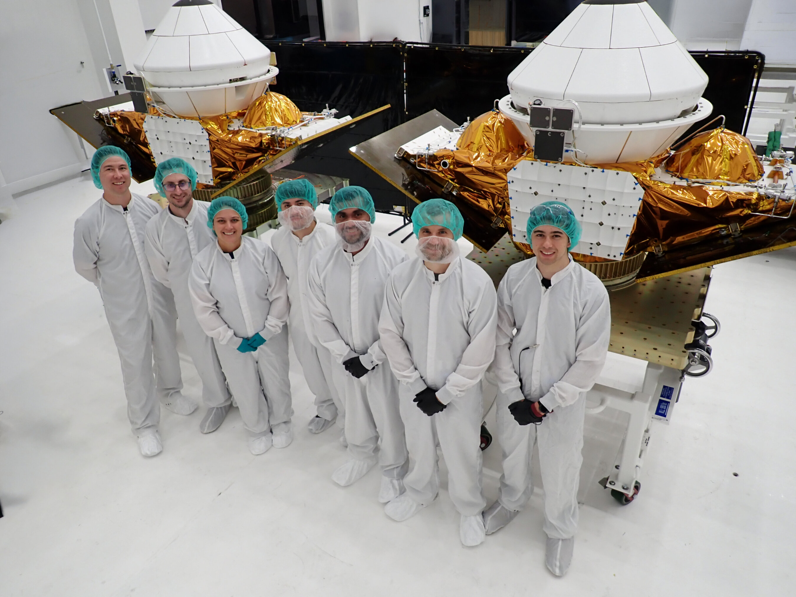
Varda announced the launch of W-8 and W-9 on SpaceX's Transporter-18 mission from Vandenberg on October 1. It was the company's first pair launched on the same rocket, although it had already operated two vehicles in orbit concurrently. W-8 carries Canopy's fiber-optic heat-shield instrumentation; W-9 includes a hypersonic navigation experiment and Syensqo material samples. The launch followed a September 30 announcement of $251 million in Series D funding. These are launch and financing milestones. The release does not establish successful returns or completed results from the new payloads.
A return capsule has an unusual business advantage: its trip home is itself a test environment. A payload can use the orbital phase, the reentry phase, or both. Reentry subjects materials and instruments to coupled heating, mechanical loads, and changing flow conditions that are difficult to reproduce together in a ground facility. That does not make ground testing obsolete. Ground facilities provide controlled, repeatable experiments; a flight provides an integrated environment with fewer opportunities to change one variable at a time. A good program uses the two kinds of evidence together.
Heat-shield recession is a particularly useful measurement because an ablative shield is supposed to change. Material loss can consume energy and alter the surface through which heat reaches the structure. The design question is not simply whether the outside became hot. Engineers need to understand how the material evolved, how much remained, and whether the underlying structure stayed within its limits. Measurements at several depths or positions can help constrain that history. A final photograph of the capsule cannot recover all the information available during the event.
Fiber-optic sensing also creates a packaging problem before it creates a data product. The sensor must remain coupled to the material it is intended to measure, and the optical path must survive long enough to be useful. A broken signal could mean a known layer has receded, a connector has failed, or an unrelated mechanical event has interrupted the instrument. Interpreting the data requires a model of the sensing system as well as the heat shield. Instrumented flight tests are valuable partly because they reveal where that model is incomplete.
Launching two vehicles together changes the operations problem more than the headline might suggest. A team now has to keep command histories, configuration versions, telemetry interpretation, and planned maneuvers unambiguous across similar spacecraft. Common software can reduce work and also create correlated mistakes. If both vehicles encounter an unexpected condition, the people on call cannot spend the same minute twice. Automation is useful when it reduces routine attention without concealing exceptions. The relevant measure is not merely spacecraft per operator, but how safely the team handles simultaneous abnormal events.
Shared launch also has a portfolio effect. Two payloads on one rocket can simplify scheduling and integration, while exposing both missions to the same launch failure. Different experiments may diversify technical risk after deployment but do nothing to diversify that initial ride. A customer deciding between cadence and concentration should care about those dependencies. This is a general operations tradeoff, not a claim about the contracted terms for W-8 or W-9. More vehicles do not automatically create more independent opportunities for success.
For orbital manufacturing, repetition is economically important because fixed work has to be amortized somewhere. Qualification, mission planning, recovery arrangements, and ground equipment are easier to justify across a sequence of paying missions than across an isolated demonstration. Yet higher cadence can expose a new bottleneck in refurbishment, payload preparation, or customer readiness. A launch count alone cannot establish low unit cost. I would look for the time between accepting a payload and delivering its material or data, including the waiting and rework that promotional schedules tend to omit.
The financing gives Varda resources to pursue that repetition. It does not prove demand for every proposed space-manufactured product, and the hypersonic-testing business should not be confused with pharmaceutical qualification. They can share vehicles while serving customers with very different acceptance criteria. The encouraging part of this week is concrete: two separately instrumented vehicles went up together. The next evidence should be equally concrete: usable measurements, successful recovery where required, and an operating process that becomes less exceptional with each mission.
Aerospace / experimental methods
NASA paints a pressure sensor onto a moving wing
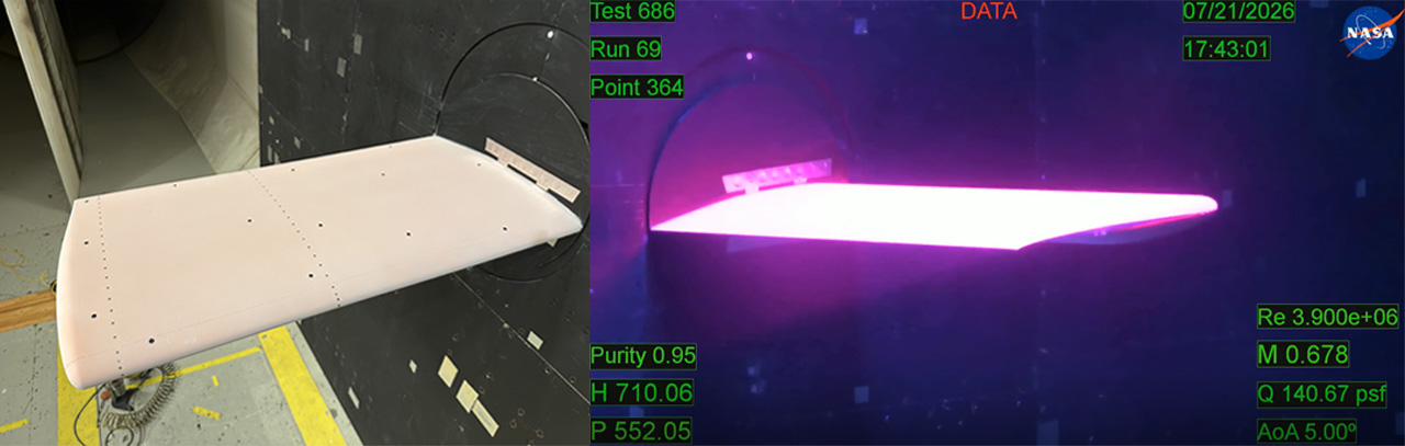
On October 2, NASA reported a pressure-sensitive-paint milestone in Langley's Transonic Dynamics Tunnel: the technique's first application to a large, freely moving model in a low-oxygen environment. The model was the Benchmark Supercritical Wing, a reference geometry rather than a prototype airliner. Ultraviolet illumination and high-speed cameras turn the coating into a surface measurement system. October 2 is the announcement date; NASA's article does not say that the physical tests happened that day. That distinction keeps a useful experimental result in the right weekly context.
The underlying trick is optical chemistry. Oxygen can quench the luminescence of an excited coating, changing the light it emits. With the gas composition, temperature, and coating response accounted for, that signal can be calibrated against pressure. A camera then collects many spatial samples at once. Unlike a set of discrete pressure taps, a coating can reveal the shape and movement of a pressure feature across a large area. The camera is not directly seeing aerodynamic force; it is seeing a signal that a calibrated model converts into pressure.
That conversion is where much of the work lives. Illumination is rarely perfectly uniform, camera sensitivity varies, and the coating can respond to temperature as well as the quantity of interest. A bright patch might reflect stronger excitation rather than a pressure change. Reference images and calibration procedures help separate these effects, but only within their assumptions. A colorful pressure map becomes persuasive when its uncertainty is mapped too. Otherwise the visual resolution can greatly exceed the resolution of what the experiment actually knows.
A moving model adds a geometric nuisance with serious consequences. The same camera pixel no longer sees the same point on the wing from one frame to the next. Perspective, distance, and angle can change the apparent brightness. Before comparing signals over time, the processing must associate measurements with material points on the moving surface. If a wing bends, a rigid image translation is insufficient. Registering the geometry incorrectly can manufacture a pressure fluctuation that is really a change in viewing conditions. Optical access does not remove the need for careful mechanics.
Unsteady measurements also need a frequency response. A camera that records rapidly cannot recover a phenomenon that the coating responds to too slowly. Exposure time, photon count, chemical response, and processing all contribute to the effective bandwidth. Shorter exposures reduce motion blur but collect less light; more illumination can introduce other constraints. The useful specification is the measurement system's response over the frequencies of interest, not simply the camera's maximum frame rate. This is the same reason a fast data logger cannot rescue a sluggish temperature probe.
For aeroelasticity, spatially resolved pressure is especially attractive. A flexible wing changes the flow, and the changed flow changes the load that bends the wing. The feedback can shift vibration frequencies and damping. A few pressure taps may miss the spatial relationship between a moving shock, separation, and the structural response. A well-calibrated pressure movie can help identify where a computational model gets that coupling wrong. It is not just a prettier version of a steady lift measurement; it can expose the sequence that produces an instability.
The benchmark geometry is an advantage rather than a lack of ambition. When several teams work on the same defined problem, disagreement is easier to localize. They can compare mesh choices, turbulence models, structural assumptions, and measured boundary conditions without also arguing about an undocumented aircraft shape. A standard experiment becomes a common debugging target. The most useful result may be a repeatable mismatch that explains why a simulation is wrong, rather than a plot that makes every curve appear to agree.
NASA points toward future tests on flexible aircraft models, not a certified new wing or an immediate fuel-burn improvement. That is the correct scale of the claim. Better measurement can make later design decisions less speculative, but it does not decide those designs by itself. What I like here is the attempt to measure a difficult coupled system without filling it with intrusive sensors. The purple glow is memorable. The real achievement is extracting a trustworthy pressure history from something that refuses to stay still.
Semiconductors / startup financing
SiMa's next robot chip still has to answer to the battery
SiMa.ai announced $150 million in Series C financing on September 28, co-led by Fidelity and Amplify, at a stated $1.45 billion valuation. The company says the round brings total funding to $500 million and supports software expansion plus next-generation IP, chiplets, and systems-on-chip. The hardware target is 1,000 dense TOPS in the first half of 2028. This is money behind a roadmap, not a thousand-TOPS chip shipping this week. The announcement does not provide a next-generation power envelope or an independently measured application benchmark.
TOPS counts operations per second under particular arithmetic assumptions. It does not specify how much useful work a robot completes. Precision, supported operators, memory access, sparsity conventions, and utilization all matter. Even the definition of an operation needs to be consistent when comparing vendors. Dense is a helpful qualifier because it avoids silently crediting work skipped through a sparsity assumption, but it leaves the rest of the comparison open. A large peak number can coexist with an application that spends most of its time waiting for data.
The roofline model is a useful first check. Performance is bounded by the smaller of peak arithmetic throughput and memory bandwidth multiplied by arithmetic intensity, the amount of computation performed per byte transferred. If a workload reuses data poorly, adding arithmetic units may barely help. A compiler can improve tiling and reuse, but it cannot make every model fit an ideal access pattern. That is why an edge processor's memory system and supported graph transformations deserve space beside its advertised TOPS. They determine how much of the arithmetic capacity the application can actually reach.
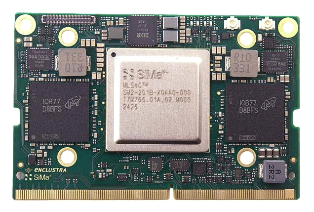
The current Modalix architecture gives a clearer picture of SiMa's approach than the future number does. Its documentation describes an Arm Cortex-A65 application complex alongside a machine-learning accelerator, an image-signal processor, and a classical-computer-vision unit on one die. The point is to handle more of the sensor-to-result pipeline in one platform. That can reduce the burden of connecting separate processors, though it does not guarantee that every stage is balanced. The accompanying board photograph shows this existing family, not undisclosed 2028 silicon.
Consider a hypothetical drone that has enough inference capacity for a larger vision model but only a fixed thermal budget. Raising sustained compute power may shorten flight time, demand more cooling mass, or force other components to operate differently. A better model could improve navigation enough to justify that cost, but the decision is a system tradeoff. The objective is not maximum TOPS; it might be completed inspection area per charge at a specified failure rate. A processor benchmark becomes useful when it helps predict that objective under realistic operating conditions.
Software support can dominate the purchasing decision. A model that needs unsupported operators may split across an accelerator and CPU, paying conversion and synchronization costs at each boundary. Quantization can improve efficiency while changing accuracy in precisely the rare cases the application cares about. Engineers need tooling that reveals those fallbacks, not just a successful compilation message. A convincing evaluation would preserve input resolution and quality targets, include preprocessing and postprocessing, and measure sustained latency and energy after the enclosure has reached its normal temperature.
Chiplets and licensable IP broaden the potential business without eliminating integration work. A customer can gain flexibility over packaging and surrounding silicon while inheriting responsibility for interfaces, validation, and supply planning. A complete SoC can be easier to adopt but less customizable. Those are different products with different buyers and support burdens. Funding all three forms is an ambitious organizational task as well as a design task. The round tells us investors are willing to finance that attempt; it does not tell us which form will produce the most durable economics.
The milestone I would watch next is not a larger roadmap number. It is a reproducible application result with the workload, precision, memory configuration, power measurement, and thermal conditions attached. Ideally, it would include the inconvenient operators and sensor processing that appear in a real deployment. There is room for specialized silicon that makes those jobs cheaper and easier. The evidence has to show the specialization surviving contact with an actual product, where battery life and integration time are usually less forgiving than a presentation slide.
A living fin, a returning capsule, a painted wing, and an edge processor all need supporting systems that are easy to leave outside the photograph. The light source steers the swimmer. Operations turn spacecraft into a service. Calibration makes the paint a sensor. Software and cooling determine whether the chip's arithmetic is useful.
Those dependencies are not reasons to dismiss the hardware. They are where the engineering becomes interesting. This week offered several concrete advances, provided we keep the demonstration, the measurement, and the commercial ambition separate long enough to understand each one.